Topology Jobs and Network Maps Overview
MSP Network Topology allows you to scan your network of devices and visualize it by building a topology map of the network. Based upon the N-able Network Topology Mapper product, the MSP Network Topology map provides you with the following information about your network:
- The monitoring status of scanned devices.
- A list of services of a N-able N-central-managed device.
- Allows you to deep link from the topology map to the device details view, if the node is successfully managed by a N-able N-central agent or probe.
Components
MSP Network Topology uses a multi-level discovery engine, which uses a combination of protocols and goes through three distinct phases to discover every node on a network and to produce a highly accurate map:
- Topology scanner
- Carries out the topology scan and provides data for the N-able N-central agent to submit it to the N-able N-central server.
- Uses a combination of ICMP, SNMP and WMI protocols to detect devices.
- Uses CDP, LLDP, Bridge table and also Spanning Tree Protocol (STP) to detect the role of each node.
Topology uses SNMP polling to retrieve CDP and LLDP data, based on the N-able Network Topology Mapper product. Please refer to this document to find out what SNMP OIDs the scanner polls for network topology information. - Enrichment service
- Retrieves additional information found during scan about individual devices that are managed by a N-able N-central agent or probe.
- Calculation
- Uses a complex algorithm to calculate connectivity between nodes.
There is additionally and API layer that delivers data to the Topology user interface, which consists of a number of pages of which two are important:
- Topology Viewer – provides an interface where you can see the Map of scanned network, inventory of devices on the map canvas, as well as a details panel that gives more information of managed devices.
There are three different layouts that you can choose to view the maps:
- Force directed
- Hierarchy
- Grid
The colors of the nodes in the network map reflect the state of the device as follows:
- Green: Normal
- Yellow: Warning
- Red: Failed
- Grey: An unmanaged device in N-central
- Topology Config – provides screens to configure topology job. The page and functionality is similar to Discovery Job pages however they are two independent entities and can not be confused.
How does it work?
The network scan begins once a topology job has been created, configured, and scheduled. During the scan, information is collected about the network devices and subnets, and the relationships among them. During the compilation of this information, the enrichment service correlates additional data such as the status, labels, and management details, and displays all of the relevant data in the topology viewer.
There is an important item to know about the results of a network scan for a topology job. The topology job will find devices from the customer or site that the job belongs to, and the results depend on the level at which the job was created. The table below summarizes these results.
| Level Topology Job Created | Result |
|---|---|
| Topology Job | Expected results. |
| Customer Level | Shows customer level and site level devices. |
| Site Level |
Shows devices as managed only if they are managed at the Site in N-central. |
In a topology map, the direction of the arrows between devices is directional, showing that one device was able to map a connection to another. The arrow head points to the device to which a connection was established. If there is no arrow head present, that means the map was able to establish the connection both ways.\
Topology mapping will not work as intended if probes are installed on Windows core servers. You will need a fully featured version of Windows Server for topology mapping to function completely.
If multiple Topology Jobs are scheduled to run at the same time, they will all be marked as "In Progress". However, only one job at a time will be processed. The others are actually queued to begin immediately after the current job completes. As a result, Topology Jobs will appear to take longer to complete than expected.
The enrichment phase is highly dependent upon the results of the discovery job. Since topology jobs and discovery jobs run independently of each other, it is possible to view a network topology with only partial information about the network. Refreshing the page will re-enrich the topology display, but the active selection or state of the interface will be lost.
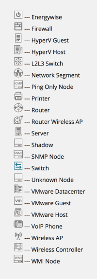
Device Symbols
There are symbols within the circles that represent the devices on the topology map.

Requirements
The following table provides the minimum requirements for using MSP Network Topology:
| Hardware/ Software |
Requirement |
|---|---|
| Operating System |
|
| CPU Speed |
2.66 GHz or faster Device discovery and map rendering are CPU-intensive. N-able recommends that you have the fastest CPU PC available. |
| Hard Drive Space | 10 GB |
| Memory | 500 MB |
| Application Framework |
.NET 3.5 SP1 .NET 4.0 .NET 4.5 |
What do you want to do?
- Learn about the best practices if you are mapping large networks.
- Create a topology job/map.
- Modify an existing topology job/map.
- View a topology map.
